Doorbell Phone
Ring a phone and create a wireless doorbell with an Arduino.
Doorbell Phone
Ring a phone and create a wireless doorbell with an Arduino.

Clean your phone with a rag dampened in one of those environmentally friendly orange based cleaners. If the bakelite is heavily worn, cracked, or sun bleached, you’re out of luck. It’s pretty much impossible to restore bakelite in that condition. Trust me. If your bakelite is dull after cleaning, you might be able to get away with polishing it with black shoe polish. As a last resort some people paint it black (I see a red door), but antique snobs will have a coronary at the mere mention of this. I say if it’s your last resort and you’re not trying to resell the phone as “mint condition”, go for it. Here’s a good site on bakelite restoration.
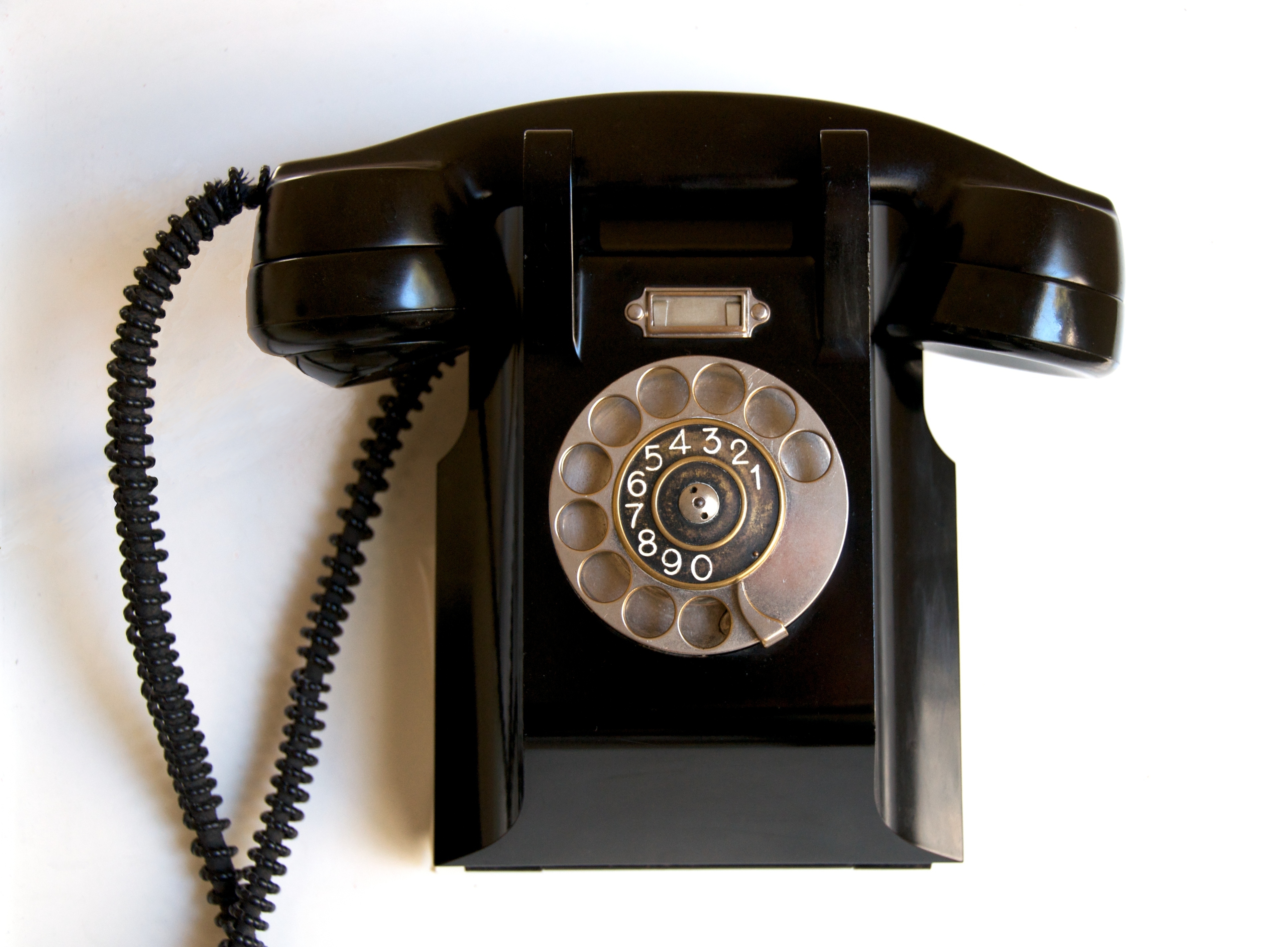
The painted numbers on my dial were chipping badly so I used a toothpick and some white Testors model paint to touch them up a little. The black paint on the dial was worn just enough to look good but not ratty so I left it the way it was. The chrome (or nickel) on the dial was tarnished so I cleaned it with some generic metal polish that was white and smelled like ammonia. Don’t rub too hard or you might take off the plating, exposing the yellow metal underneath.
As long as the ringer works you can ignore any other electrical problems with the phone, we don’t need to use the dial or handset. It’s possible that in a future version of this project we would want to use them because the phone interface board (more on that later) has the capability, but for now we’re keeping it simple.
Restore the phone
Program the Arduino
As I mentioned a while back, if you’re able to fit all the receiver electronics inside the phone it will need to be mounted near a power outlet. If you put the electronics in an external box the box will need to be near a power outlet, while the phone can then be anywhere within reach of a phone cord connecting the two. If you have an ugly box you’ll want a location out of the way so you can hide it in a cabinet or behind something.
Mount everything
Owen Morgan writes:
“I have good luck restoring Bakelite using the methods on the following website:
http://web.ukonline.co.uk/freshwater/bakelit1.htm
Paste wax has been a winner for me, it is fairly gentle and doesn’t contain any harsh chemicals.”
Thanks to everyone who wrote in with their compliments!
Do you like this project or have suggestions on how to make it better? Do you want me to build one for you? Do you need tutoring on Arduinos, programming, and basic electronics?
Email me: btz at bryan zimmer dot net.
Follow Up
If you’re using a wall phone and you’re a renter like me, you need to get creative. Your landlord probably won’t appreciate you drilling holes in her walls so you can mount the phone like a normal human being. Instead, try mounting it on the side of some shelves, cabinet, or other vertical surface you own. You could get some strong velcro with a glue backing from your local hardware store and mount the phone to the cabinet. The only problem is that if you get tired of the phone you’ll probably have trouble removing the velcro from the cabinet thanks to the glue.

If you’re able to fit all the receiver electronics I mention later inside the phone it will need to be mounted near a power outlet. If you put the electronics in an external box, the box will need to be near a power outlet while the phone can then be anywhere within reach of a phone cord connecting the two. If you have an ugly box you’ll want a location out of the way so you can hide it in a cabinet or behind something.
Mount the phone
Once upon a time my girlfriend found an interesting looking old phone for sale in one of those fancy French boutique-type catalogs. Their description:
“Not a reproduction, but a 1940's Swedish-made Ericsson bakelite original. Fully restored, with new wiring and microphone, nickel-plated rotary dial and authentic ring. Refurbished in Argentina.”
A brief background: Bakelite was the precursor to plastic, and was used to make a large percentage of phones and radios in the first half of the 20th century. This model (Ericsson DE 200) was actually from the mid-30’s, but whatever, I’m just a detail snob. They’re incredibly hard to find, and information about them on the internet is scarce.
Back to the story. I’m a sucker for cool looking antiques that are functional and still useful, so I was intrigued. Companies don’t put the same aesthetic design effort or build quality into their products these days, which is part of the reason why I like antiques. And who doesn’t like that hearty, crisp, old-timey sound of an actual bell ringing in a phone? Not this red blooded American, I’ll tell you that. I was just about to buy it when I saw the price. $395! Highway robbery!
Being the Do It Yourselfer and cheap bastard that I am, I headed to eBay to find one I could restore myself. Lucky for me someone was selling one and I picked it up for $10. I’ve only seen one other on eBay in the year since then, at it went for a lot more. I’ve seen websites that deal in antiques with a few for sale, typically for over $150. Suckers.
Seeing as how we didn’t have a landline anymore I had to come up with something useful for this phone to do. Our current doorbell is one of those cheap electronic ones with the boring “ding-dong” sound, so modern and homogenous. Thus, the new life for this phone was decided. It would have to be wireless because I’m a renter and can’t permanently alter the house, and the current doorbell button wasn’t in a location where I could easily run new wire. The only other requirements were that the new button would have to look cool in a retro way, and the phone would have to be mounted non-permanently on a wall or other vertical surface.

You can use a breadboard for the support circuit if you’re not into soldering. If you want something smaller, more permanent, and reliable pick up some prototyping board (some people call it perf board) and solder this baby up.
Connect the AG1170, support circuit, and Arduino
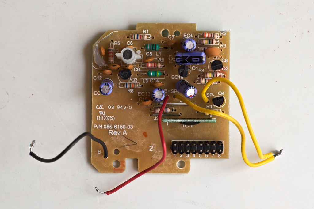
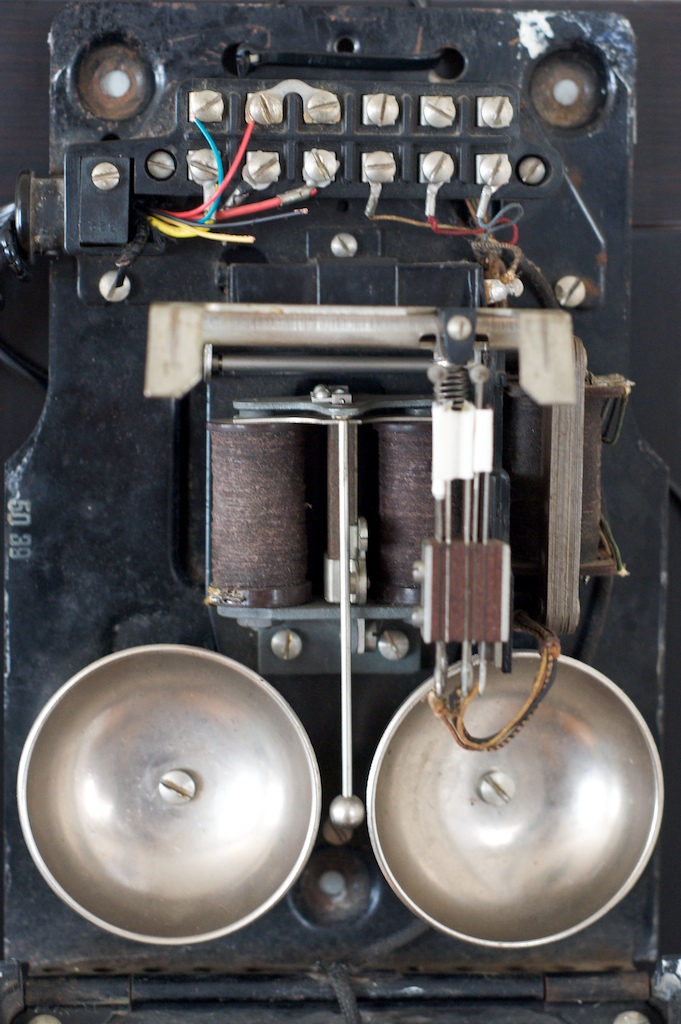
Take apart the doorbell receiver


You’ll also need to get an LED and resistor. I went with this LED, but any one with a 3.4 volt forward drop and max current of 20 milliamps should work. If you go with an LED that has different specs you’ll need to change the resistor value to match. When I need to figure that kind of stuff out I cheat and use this site to calculate it for me.
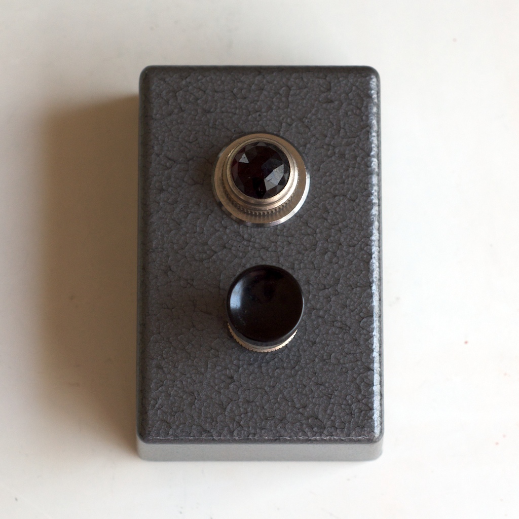
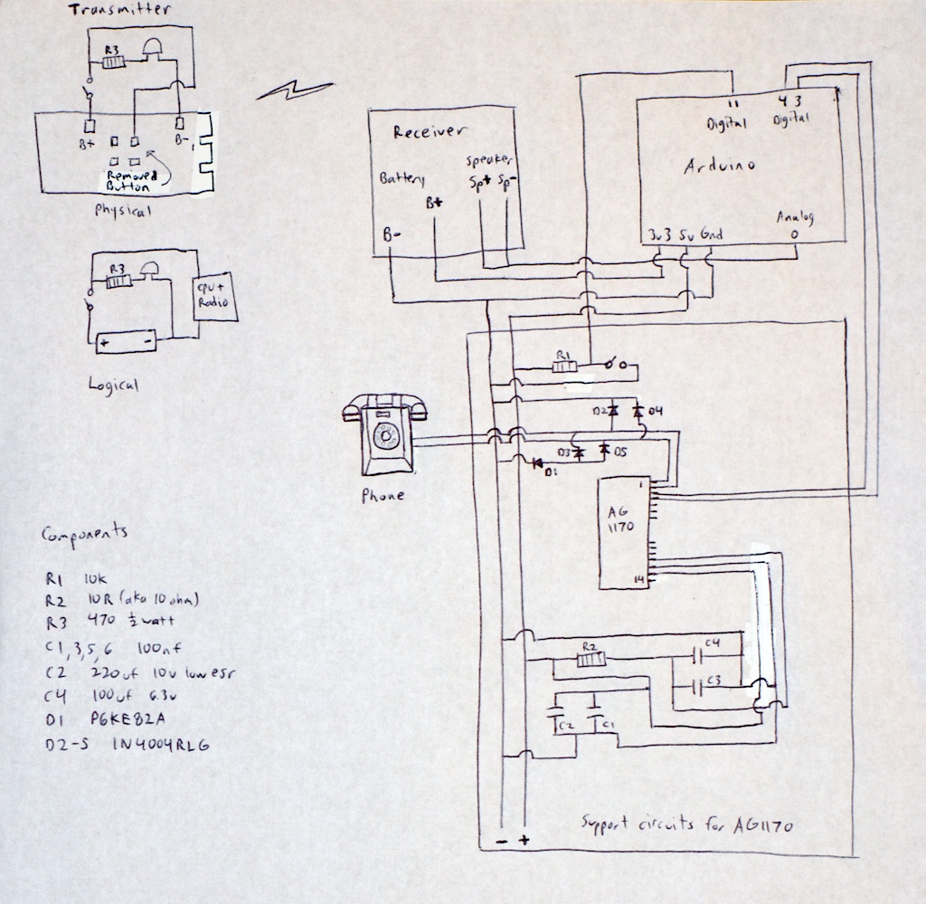
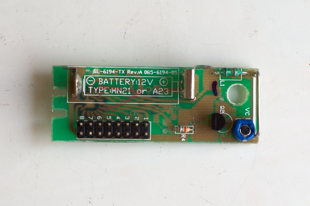
Build the new transmitter
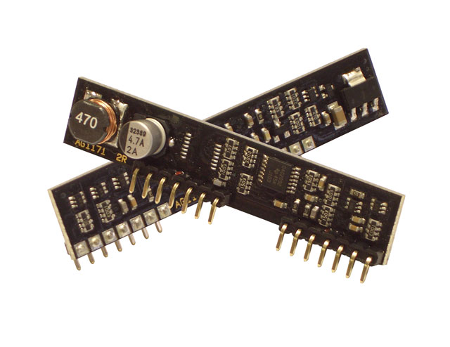
One day, the clouds parted, a beam of sunlight shone upon my weary eyes, and I found salvation. A random post on some obscure electronics forum said searching for “ringing SLIC” (subscriber line interface card) might help, and boy did it ever. I found Silvertel, and they had exactly what I was looking for, a small, 5v powered, inexpensive board that would ring a phone. It will do more than that, but that’s for another project. I went with their AG1170-S5 instead of their other models because it supplies more power to the phone, I didn’t need an adjustable line impedance since I’m in the US, and I wanted as small a board as possible. The datasheet is here. I went with Silvertel because they were easy to find, their product did everything I needed it to and then some, they don’t require you to buy large quantities, their support was responsive and knowledgeable, and the board only cost me $7! That was barely more expensive than the DIY solutions, and many times cheaper than the other commercial solutions.
Note: I’m not a Silvertel employee, I don’t own any of their stock, and they haven’t given me any kickbacks (yet). I just like their product.
All hail the AG1170
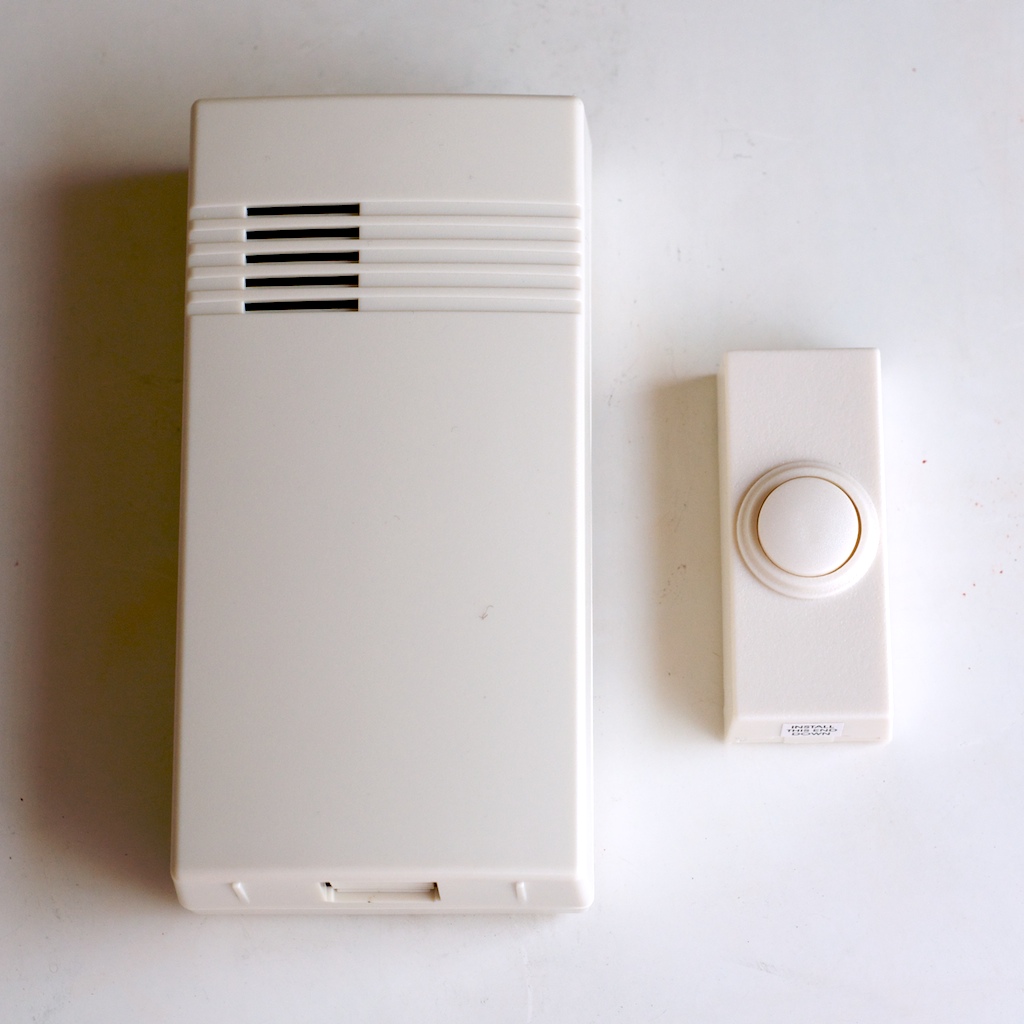
Make sure both the transmitter and receiver are set to the same ID/security code with the little black jumpers inside both. The manual in the package can help. Right out of the box this isn’t a problem because they’re both set properly by the factory, but you may want to change the code if your neighbor has a similar doorbell or yours seems to ring randomly.
Buy the doorbell
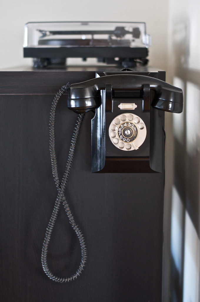
If your phone is like mine and has bells in it you’ll probably need to adjust them to get the right sound. The AG1170 doesn’t have quite as much ringing power as the phone company, so you’ll want to loosen the screws holding the bells down so they ring more easily. Keep ringing the phone while tightening and loosening the screws to get your desired tone and volume.
Test
So what is all this voodoo that rings a phone when you press a button? Pushing the button on the transmitter connects the circuit to the battery, lighting the LED and sending a signal to the receiver. The receiver gets the signal and rings what used to be its speaker. That speaker connection now goes to an input (wirelessRingPin) on the Arduino. The Arduino sees the pulse from the transmitter and gets the AG1170 ready to ring the phone by turning on ringModePin. The Arduino turns one of the connections to the AG1170 (forwardReversePin) on and off 20 times a second (20 hz), which is the normal US phone ring style. The AG1170 amplifies this signal to 70 volts, which is what the phone needs to power its ringer coil. The Arduino rings the phone twice, then waits for someone to push the button again.
How does it work?
The AG1170 has other features I haven’t used yet, like detecting numbers dialed with a rotary phone and passing voice and DTMF tones to an external circuit. In other words you can interact more with the phone. Maybe when someone rings the doorbell you want to dial 1 to activate a relay to open the door, or dial 2 to open a trap door, or dial 3 to release the hounds. Maybe you want to put a microphone and speaker in your transmitter outside, and when you pick up the phone you can talk to the person before you open the door. I might eventually add those features, but I need to get a few other projects out of the way first.
The Future
