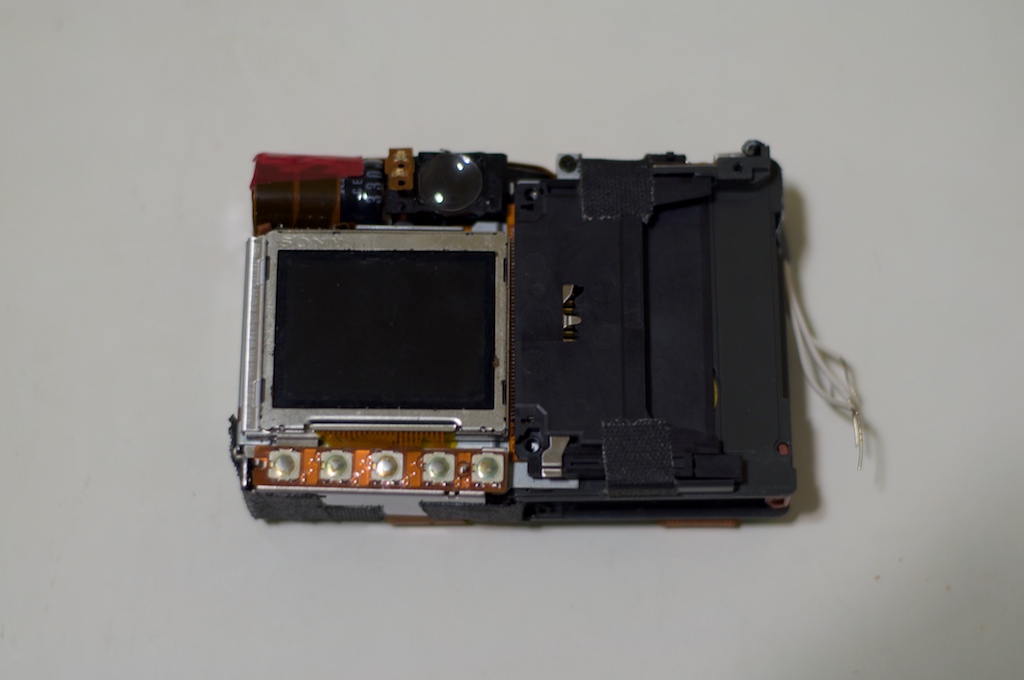
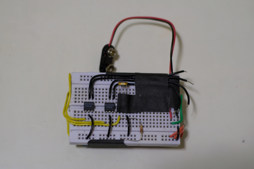
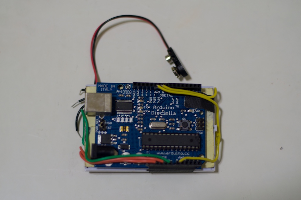
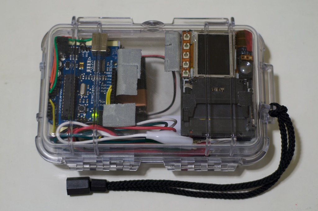
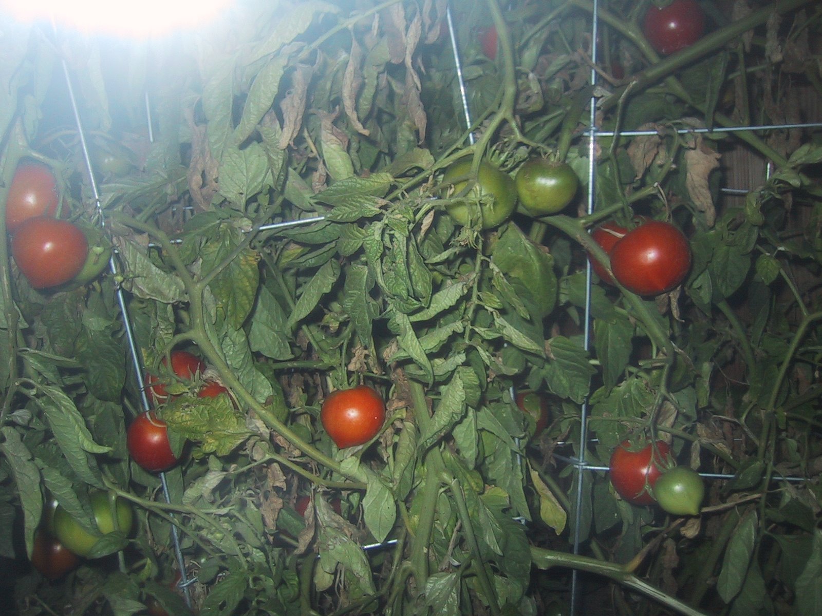
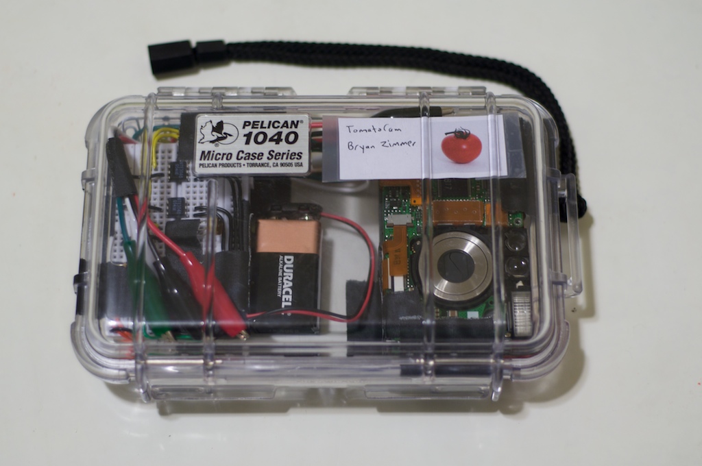
Recently a friend of mine had a problem with something mysteriously eating holes in her tomatoes during the night. She vetoed my original idea of solving the problem with DDT and an electrified cage, so I went with a sentry camera. At first I thought I would go with some sort of infrared night vision motion-sensitive camera, but that would require buying or modifying a camera, buying an IR spotlight, and building a Linux system with a video capture card to to run ZoneMinder. Then I remembered I had an old Canon PowerShot S110, assorted electronic components, and my favorite digital Swiss Army Knife, the Arduino.


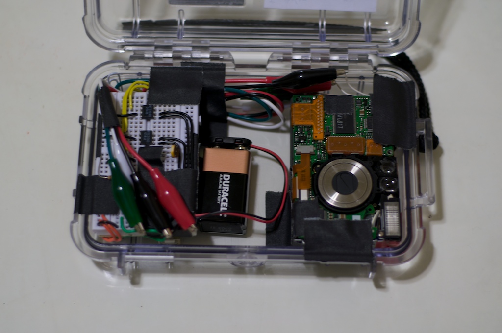
I whipped up a camera that would wait until it was dark, turn itself on once an hour, take a picture with the flash, and then turn itself off. It worked surprisingly well, and in the process of building it I learned about optoisolators, tomato farming, and where babies come from.

Tomato Cam

How to create a time lapse camera with an Arduino.

Take off the outer shell of your camera. If you don’t have a Canon PowerShot S110 you can substitute almost any digital camera, you’ll just have to figure out where the power and shutter buttons are connected on the inside.


My camera had been sitting completely disassembled for a couple of years, but luckily I was able to piece it back together. I didn’t want to go to the trouble of figuring out where all the screws were supposed to go so I put it back together with gaff tape, my favorite sticky Swiss Army Knife. If you like duct tape, go ahead and treat yourself to some gaff tape.
 

Disassemble the camera

Connect all the breadboard parts according to this picture. There’s a schematic below with more information. I like to keep things clean and organized because it helps with troubleshooting later, and I’m anal.


Connect all the Arduino parts according to this picture and the schematic. Make sure you set the Arduino power jumper below the USB connector to External so it gets its power from the 9 volt battery on the breadboard. Mount the Arduino to the back of the breadboard.
 

Connect the breadboard and Arduino

Open the Arduino sketch and upload it to your board. The sketch is here. The Arduino environment is here if you don’t already have it.
 
The photoresistor was one I had lying around, it measured 200 ohms in bright light. If you use a different one just change the “dusk” variable in the Arduino sketch to your desired light level through experimentation. The debug output sent to the Arduino console will tell you what the reading is.


Optoisolators are basically switches that allow one circuit to turn another on and off without the two being electrically connected. The Arduino turns on the optoisolator, which turns on an LED hidden inside. The light from that turns on a light-sensitive switch inside, which then controls the camera. I used an optoisolator to prevent any chance of the camera and Arduino frying each other, and because it was something new to learn about. And saying optoisolator makes you sound fancy.


Program the Arduino

Schematic

Mount everything in a Pelican 1040 Case, or whatever transparent container you have. It’ll need to be weatherproof or
your camera might not make it through the night. You’ll need to mount everything to the back of the case so that the lens can extend when it turns on. Gaff tape is your friend yet again, but you could also go with velcro. Make sure you don’t get any of the case ridges in front of the lens. I used alligator clips to connect the Arduino, breadboard, and camera, but you could use plain old wires to save space.
 

Regulators mount up

Power it on and try it out. When the battery is connected the Arduino will wait 5 seconds and take a test picture. It will then wait until it’s dark out and take picture every hour after that. If you’re testing during the day don’t forget to cover the light sensor or nothing will happen after the first test picture.


You may want to change the “dusk” variable in the Arduino code, depending on how dark it is in your area and what value photoresistor you used. The default should work for most people though.


A standard 9 volt battery should last one night. I recommend going the environmentally friendly route and getting one that’s rechargeable. You can use a larger capacity (greater milliamp hour) battery but remember that the Arduino needs between 7-12 volts.


My friend’s Tomato Cam demo site:

http://tomatocam.blogspot.com


Do you like this project or have suggestions on how to make it better? Do you want me to build one for you? Do you need tutoring on Arduinos, programming, and basic electronics?

Email me: btz at bryan zimmer dot net.


Test

Connect some short lengths of wire to the positive and negative contacts of the camera’s power and shutter buttons. I highly recommend soldering them (gently), but you might be able to get away with alligator clips. Try learning to solder if you haven’t yet, it’s not as bad as you think. Hell, if a lazy klutz like me can learn so can you.
 

Connect the triggers